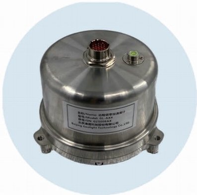
The GL-AX4 Remote Zeroing Accelerometer features an electromechanical integrated design, housing three directional mechanical pendulums and a force-balancing feedback circuit within a 304 stainless steel sealed enclosure measuring φ140mm×110mm. Mounted on a dedicated stainless steel base plate, the accelerometer is securely anchored to the observation instrument pedestal using an expansion bolt, ensuring simple and convenient installation and removal. The base plate offers horizontal adjustment capabilities and automatic compensation for 5-degree bolt tilts. It supports both temporary placement (for trial testing) and permanent fixed installations.
The GL-AX4 Remote Zeroing Accelerometer employs force-balanced electronic feedback technology, featuring a wide dynamic range, broad frequency bandwidth, and excellent linearity. It provides remote zero-point calibration capabilities: users can remotely calibrate its zero point through seismic data acquisition or adjust it using strong-motion observation data from free-field seismic monitoring. The calibrated zero point remains below 10mV. This device is suitable for free-field strong-motion observation, structural vibration monitoring of buildings and structures, as well as dynamic vibration monitoring of facilities such as dams, bridges, stations, and tunnels.
▶ Structure: three-way integration, force balance electronic feedback;
▶ Measurement range: ±4 g;
▶ Full scale output: ±10 V, double end differential output;
▶ Sensitivity: 2.5 V/g, double end differential output;
▶ Sensitivity error: ≤3%;
▶ Observation direction: vertical/UD, east-west/EW, north-south/NS;
▶ Dynamic range:>150dB;
▶ Bandwidth: DC~100Hz (can be expanded to 180Hz);
▶ Bandwidth characteristic error: 03 dB~03dB (0.1~ 50H vibration table calibration) -3dB~1dB (50Hz~80H, vibration table calibration);
▶Output resistance: <10Ω
▶ Maximum load capacitance: 0.01 μF;
▶ Maximum output current: yes;
▶ Horizontal sensitivity ratio: ≤1%;
▶ Linearity: better than 1%;
▶ Temperature drift: <500×10-6 gn/℃;
▶ Zero point query:The zero point is automatically read in real time remotely through the seismic data collector
▶ Zero adjustment function: send instructions remotely through seismic data collector to automatically adjust zero
▶ Calibration function: calibration voltage input range-3~+3V
▶ Damping calibration function: Yes (single line level control)
▶ Voltage calibration constant: 5 ms-2
▶ Power supply voltage: +9~36 V DC single power supply
▶ Overall power consumption: <0.7W (supply voltage +12V static)
▶ Interface standard: meet the relevant requirements of DB/T13 “Ground Vibration Observation-Interface and Control”
▶ External dimensions: 1 4 0 mm×110mm
▶ Weight: about 3.0kg
▶ Operating environment: temperature-25℃~60℃, humidity less than 98%;
▶ Waterproof index: IP68;
▶ Shell material: 304 stainless steel;